Learn the differences between ESD solid vinyl tile and interlocking ESD tile. The post compares specs, installation, maintenance and intangibles.

Case Study: ESD Flooring Failure, Incorrect Testing: Always Qualify Your Floor Using ANSI/ESD Test Methods
7 min read, 11 min videos
Note: This information pertains to flooring concerns associated with ESD protected areas (EPAs) in electronics manufacturing and handling. This information is not pertinent to static-control concerns in end-user environments. If your interest focus is on ESD flooring for data centers, server rooms, 911 call centers, school labs, networked offices, FAA flight towers, communication rooms or telecommunication areas – go to this page for technical articles
ANSI/ESD S20.20 provides specific test methods to qualify and evaluate ESD flooring materials. Other methods – such as European test methods or NFPA methods – yield results that differ from and are incompatible with ANSI/ESD test results. While a material may pass European or NFPA tests, the floor may still fail to comply with S20.20. The only way to ensure that your ESD floor complies with relevant standards is to test according to test methods in S20.20. For best results, require tests performed by an independent lab.
THE GIST: ESD Flooring Failure, Incorrect Testing
- An improperly installed vapor barrier will not adhere to the subfloor.
- When the bond between vapor barrier and subfloor fails, the tiles will lift.
- Ensuring a strong bond requires due diligence:
- Take a core sample
- Perform a bond test
- Investigate type of building construction
- With a good bond, the tiles will not lift – even with a chisel.
- Get the tile manufacturer involved.
Case Study: ESD Flooring Failure, Incorrect Testing
A military defense contractor (electronics application), trying to meet static-control requirements in ANSI/ESD S20.20-2014, contacted us about a problem they were having with their new ESD floor. They had purchased the new floor under the assumption that it would meet all the requirements of Table 2 in the S20.20 document.
The caller explained that the floor wasn’t meeting any of the requirements – even though the manufacturer had assured them nothing was wrong with the flooring. The client described the floor as a static conductive linoleum sheet floor. Made in Europe, the floor was new to the US market. After reviewing the client’s test data, we agreed to meet with and help them find out why the floor wasn’t doing what it was supposed to do.
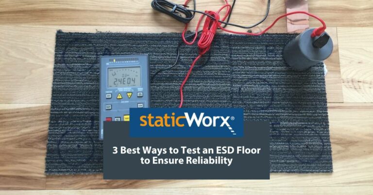
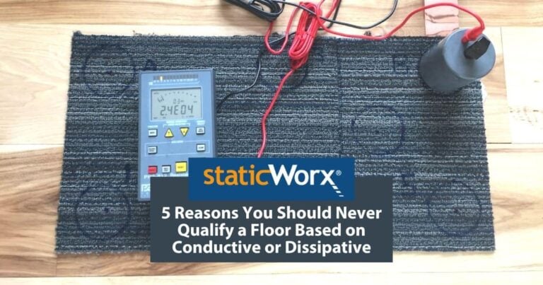
Immediately after arrival, we were asked to measure the floor with our Prostat megohm meter.
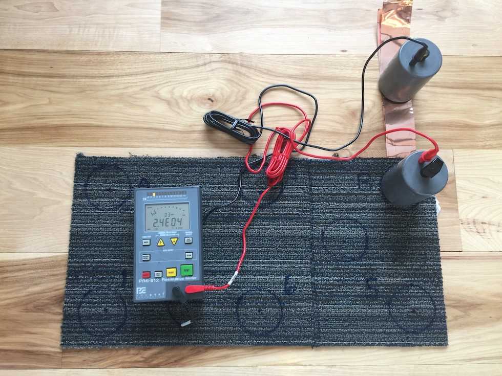

After several tests, we quickly concluded that our meter and theirs were arriving at consistent results. The floor was incapable of meeting any of the S20.20 requirements: it was far too resistive.
The resistance to ground exceeded 1 billion ohms (1.0 x 10E9) – the upper limit in the S20.20 resistance standard.
The building representative was extremely agitated. He knew it would be difficult to shut down the facility and replace the floor. The client admitted that the floor had been a value-engineered substitution, selected late in their project. The manufacturer had guaranteed them that the floor would do everything the originally specified floor was supposed to do.
Under the guidelines in ANSI/ESD S20.20, we use Standard Test Method 7.1 to test for electrical resistance.
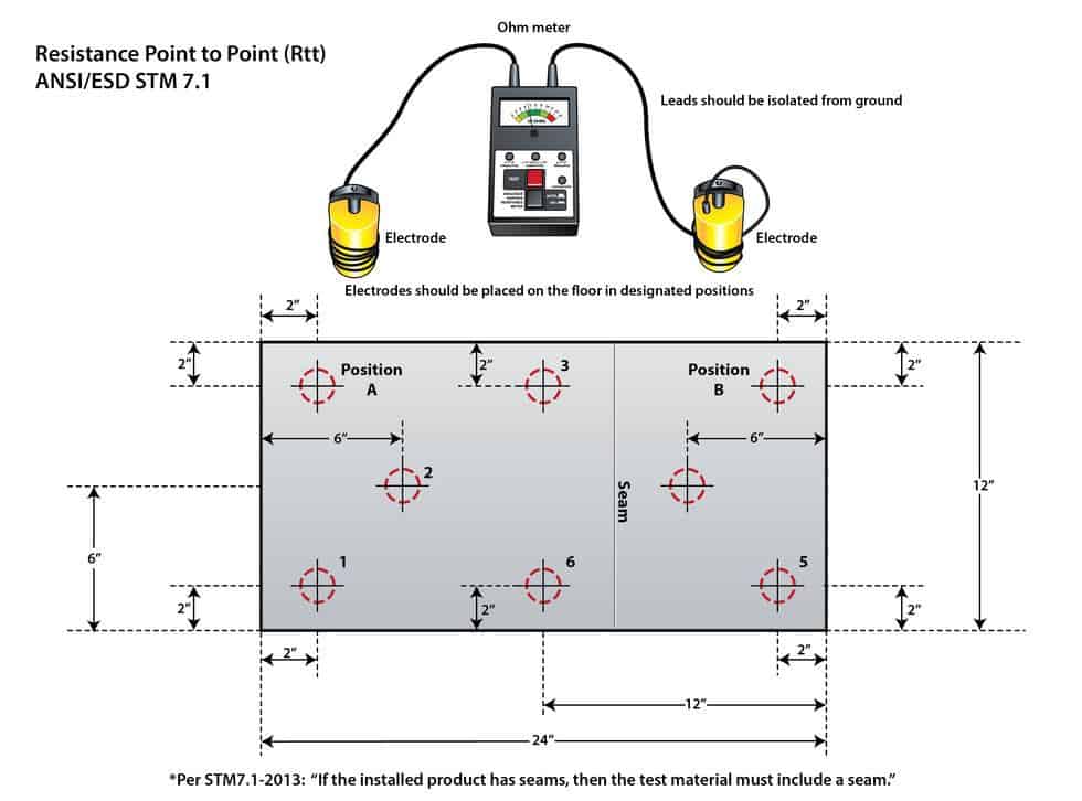

Upon review of the floor manufacturer’s documents, we discovered the real problem with the floor: the manufacturer’s specifications referenced a resistive properties test method used in Europe. Unlike North American standard test method ANSI/ESD S7.1, the European method tests for electrical resistance using a much higher applied voltage of 500 volts.
According to Ohms Law, higher applied voltages result in lower electrical resistance measurements. In other words, the more voltage you apply, the lower ohms resistance you will see.
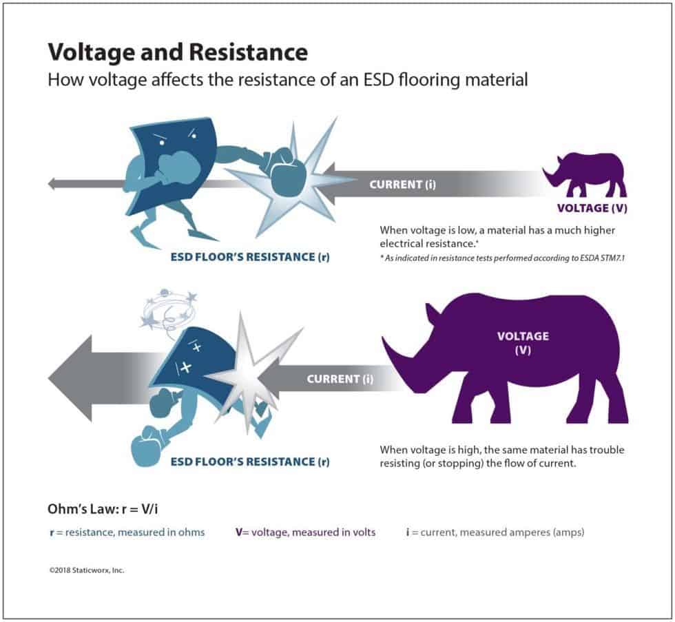

Following the European test method, the resistance reading appeared much lower than, in fact, it actually was. At an applied voltage between 10 and 100 volts, required by ANSI/ESD S20.20, the resistance measurement was extremely high. Unfortunately for this end user – because no one in their organization had picked up on the test methods referenced by the European manufacturer – they were probably stuck with the floor. The test method was clearly printed on their spec sheet.
There was one other forewarning this client had missed. Despite the reference to a static dissipative value < 1.0 x 10E8 ohms, the manufacturer’s brochure recommended the floor for “areas with sensitive equipment.” Their generic recommendation made no reference – on any of their promotional materials – to electronics manufacturing, EPAs or ANSI/ESD S20.20. There was also no mention of a lifetime static-control warranty.
Conclusions
- Only accept materials that have been specified using ANSI/ESD Standard Test Methods: www.esda.org
- Test for electrical resistance, according to test method STM 7.1
- Test for walking body voltage (charge generation) according to STM 97.1
- Always ask for test data from independent labs when qualifying any kind of static-control flooring.
- Labs like Fowler Labs can perform the full battery of tests needed for qualifying floors to the requirements in ANSI/ESD S20.20.
- Insist on a lifetime static-control warranty.
- Always include in your contract a requirement for post installation tests – demonstrating that the flooring meets Method One in ANSI/ESD S20.20 for Personnel grounding.
- Method One requires ANSI/ESD S97.1 System resistance testing. ANSI/ESD S20.20 confuses many engineers; without reading closely, it’s easy to conclude that the floor merely needs to measure below 1.0 x 10E9 using test method s7.1-2005. This is a fallacy.
- The floor must also meet charge generation requirements. For electronics facilities, the floor may not generate more than 100 volts of static electricity; for Class-0 electronics the upper limit is 10 volts.
You might also take a look at this video for further understanding. Static dissipative versus conductive:


Further Resources

About StaticWorx, Inc
All StaticWorx posts are written by our technical team and based on industry standards and specifications, test data, independent lab reports and other verifiable data. We provide ESD training and offer CEU credits to architects. If you’re interested in an ESD training session or our architects’ ESD workshop, give us a call: 617-923-2000.
Get in Touch
The form below will help us better understand your needs and get you as quickly as possible to the right person. We look forward to helping you solve your static problem!
You can expect a response within 24 hours. For faster service, please give us a call: 617-923-2000
"*" indicates required fields
Visit our privacy policy to find out how we process data.
More Blog Posts
To maintain performance, ESD floors require specially formulated products. We offer tips on what to consider when choosing cleaning supplies.
Static-dissipative floors transport harmful static charges to ground. Dissipative is also a term for flooring with a specific, measurable electrical resistance.
StaticWorx recognized as one of the fastest growing private companies in the U.S. 2023 marks StaticWorx fourth appearance on Inc. 5000 list.
Conductive and dissipative flooring protect electronics by transporting charges to ground, conductive at a quicker rate, dissipative slower & more controlled.
We explain the 3 main ways to test an ESD floor: Electrical resistance; body voltage & ESD audits, with advantages and reasons for each.
Three critical factors—application, industry standards & footwear—help you choose the best ESD floor, while ensuring the safety & efficiency of your operations.
StaticWorx Founder and President Dave Long shares three of his recommended reads: Quit, How to Change, and The Goal.
There are leadership qualities StaticWorx strives to embody every day, with every product, throughout each project.
No matter how you slice and dice a project, an ESD floor is a major investment. This blog post examines five ways to keep undue costs down.
What’s the difference between static control and static resistant? Or anti-static flooring? Find out more in our blog post.
A major part of any ESD control program is getting proper flooring in place. How can one replace a floor without generating any debris? Learn more.
A well-designed, comprehensive, fully realized program is a must for manufacturers serious about ESD control. Learn why ESD programs fail.
ESD Floors should never be specified based on the descriptive terms conductive or static dissipative. Always base ESD specs on verifiable metrics. Find out why.
<a class="eael-grid-post-link" href="https://staticworx.com/installing/esd-flooring-installation-bond-test-manufacturer-oversight-critical/" title="Blog Post: ESD Flooring Installation:
Bond Test and Manufacturer Oversight Are Critical to ESD Flooring Success">Blog Post: ESD Flooring Installation:
Bond Test and Manufacturer Oversight Are Critical to ESD Flooring Success
If the vapor barrier fails to adhere to the subfloor, tiles will lift. Bond test and manufacturer oversight are crucial to ESD floor installation success.
<a class="eael-grid-post-link" href="https://staticworx.com/technical-info/conductive-static-dissipative-flooring-difference/" title="Blog Post: Conductive and Static-Dissipative Flooring: What’s the Difference?
The Layperson’s Answer">Blog Post: Conductive and Static-Dissipative Flooring: What’s the Difference?
The Layperson’s Answer
What’s the difference between conductive and static-dissipative flooring? Facts, analogies and images illustrate the difference in easily understood terms.
Qualifying an ESD floor helps ensure you get the floor you paid for. Find out why you should always qualify according to ESD S20.20
Qualification is the first step in selecting an ESD floor. Learn how to perform resistance tests to be sure the floor meets electrical & safety standards.
Will bare concrete control static? Learn why concrete floors are unreliable & what precautions to take if you must work on a bare concrete floor.
A look at how the StaticWorx cartoon, 'Conductive Flooring Does Not Mean Antistatic Flooring,' was conceived and created.
Learning Center Articles
- ESD Basics
- Installation & Maintenance
- Selecting & Specifying an ESD Floor
- Technical Information
- 7 Common Mistakes Selecting an ESD floor
- A Guide to ESD Flooring Selection
- Avoid Costly Failures: What You Need to Know When Specifying ESD Flooring
- Choosing ESD Flooring for:
- ESD Footwear: What Is It and When Is It Necessary?
- ESD Footwear for Electronics Manufacturing and Handling Applications
- Facility Managers’ Guide to Selecting ESD Flooring
- The Need for Due Diligence in Specifying Static-Free Flooring
- Standard of Care for Specifying Floors in Mission-Critical Spaces
- Understanding the Hidden Costs of ESD Flooring

StaticWorx high-performance static-control floors protect electronic components, explosives, and high-speed computers from damage caused by static electricity. ESD flooring is part of a system. Choices should always be based on objective, researched evidence. When you partner with us, we look at all possible items that may need to integrate with the floor, and, focusing on your goals and objectives, help you find the right floor for your application.


