
Understanding Grounding Standards
Post Summary
Resistance standards are industry-specific. Learn grounding standards for mission-critical spaces, how they differ from ANSI/ESD standards, & how to test and evaluate ESD flooring.
Need additional information about StaticWorx products? Learn more about our ESD flooring products.
We use electrical resistance tests, measured in ohms, to evaluate the conductivity of a floor or flooring material. Within the A&D community, confusion exists over which electrical resistance rating is correct for static-control flooring used in mission-critical spaces, such as communication and data storage environments, FAA flight towers, critical call centers, 9-1-1 dispatch centers, server rooms, and other end-user environments where operational* equipment is in use.
* Operational equipment is the same as energized equipment.
The confusion stems from the fact that ESD flooring standards—written for ESD-protected areas (EPAs) in electronics manufacturing and handling environments, as well as spaces where explosives or flammable materials are handled—are different from standards for the telecommunications and data center industries. The grounding and surge-protection standards of the latter focus on the unique needs of a 24/7 mission-critical environment.
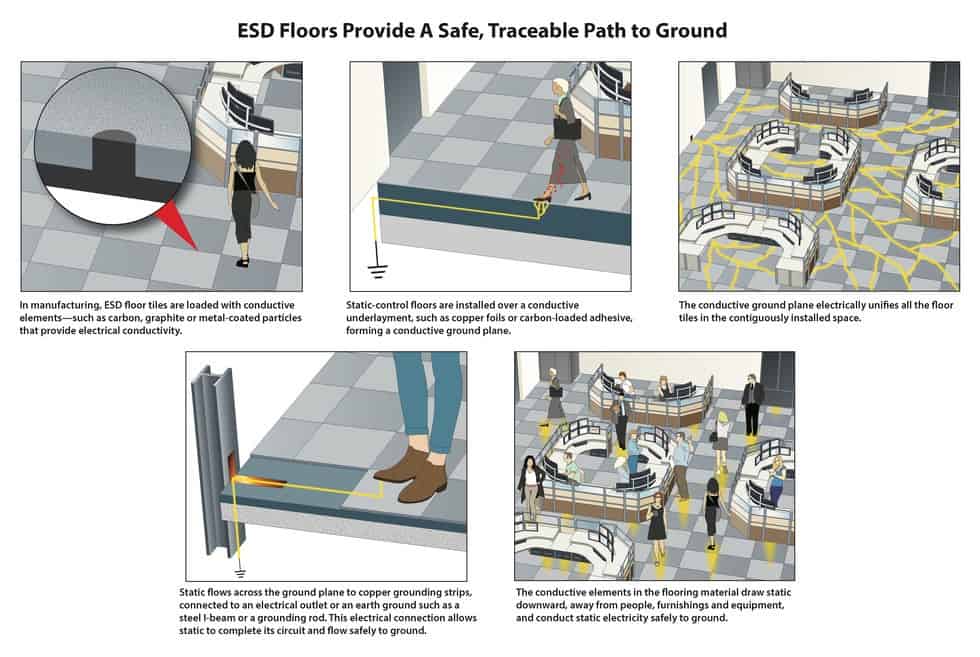
In these environments, ESD flooring prevents static buildup on people and chairs and dissipates static charges safely to ground, preventing electrostatic discharge events that can disrupt data or damage or destroy the circuits inside sensitive electronic equipment.
To ensure the safety of people and equipment, the floor must be properly grounded, using recognized electrical standards.
Grounded Floor
Below we’ve outlined the electrical resistance standards set by the computer and telecommunications industries, the Federal Aviation Administration (FAA) and UNINETT, a working group on physical infrastructure. These standards should lay to rest any misconceptions about the proper electrical specifications of floors—particularly ESD carpeting*—installed in environments where static-sensitive operational equipment is used.
* StaticWorx does not recommend ESD vinyl or epoxy coatings for mission-critical spaces: vinyl and epoxy are inherently static-generating materials. Even with good electrical resistance, without the required and regimented use of special ESD-footwear, a grounded vinyl or epoxy floor will generate significant static charges.
Electrically conductive (EC) rubber maintains its static-control properties over time. Because of its material makeup, EC rubber does not pose the electrical safety issues that can be problematic in overly conductive static-control carpeting or carpet tiles.
By the Numbers
Many ESD flooring suppliers incorrectly assume that conductive flooring measuring between 2.5 x 10E4 and 1.0 x 10E6 is acceptable for end-user environments. These numbers come from unrelated requirements for the mandatory use of conductive flooring in operations where explosives and flammable materials are manufactured or handled.*
Since DoD standards require conductive flooring for handling ordnance and flammable materials, it is falsely extrapolated that conductive flooring must be better than static-dissipative flooring for any application.
* Operations where explosives are manufactured or handled have enforced mandates requiring all personnel in the space to wear ESD-protective footwear. The built-in resistors in ESD footwear prevent the wearer from exposure to electrical shocks.
Explosives-grade flooring does not comply with grounding standards for flight towers or telecommunication spaces. In end-user environments—where people do not wear special ESD footwear—highly conductive flooring (below 1.0 x 10E5) can pose unnecessary risks.
The five major standards-setting authorities for these spaces, including the FAA and organizations for the computer and telecommunications industries, all require flooring in end-user spaces with electrified equipment to measure above 1.0 x 10E6 and below 1.0 x 10E9.
Download the free Flooring Selector guide.
Reminders of Note
Below, we’ve listed the standards organizations with their recommended parameters. As you review the recommended electrical parameters, keep in mind 4 factors:
- Every standards organization approves the use of materials measuring in the static-dissipative range—i.e., between 1.0 x 10E6 and 1.0 x 10E9.
- Many standards organizations reject the use of floors measuring in the conductive range—i.e., less than 1.0 x 10E6.
- When evaluating scientific notations, bear in mind that the difference between each ascending exponent is a multiplier of 10. For example: 1.5 x 10 to the 4th (1.5 x 10E4) = 15,000 ohms. 1.5 x 10 to the 5th (1.5 x 10E5) is 150,000 ohms.
- A floor measuring between 2.5 x 10E4 and 1.0 x 10E6 is defined as a conductive floor. A floor measuring between 1.0 x 10E6 and 1.0 x 10E9 is defined as a static- dissipative floor.
Resistance Standards by Standards Organization / Applications
IBM Publications Center
- IBM site recommendation and physical planning
- This is a common document referenced by data center designers
- IBM’s Recommended resistance range for flooring:1.5 x 10E5 – 1.0 x 10E10 ohms Please note: StaticWorx does not recommend the use of floors measuring above 1.0 x 10E9. Time and environmental conditions—e.g., temperature, moisture, and humidity (RH)—can change resistance measurements. If the resistance of a floor measuring 1.0 x 10E10 were to rise, the floor may not have sufficient electrical conductance to discharge static electricity.
Motorola R56
- Motorola R56
- The Motorola guidelines are the recognized standard in the telecommunications industry and are the most complete and rigorous specification for protecting communication equipment used in public safety and commercial communication sites. R56 is the grounding standard used by engineers and architects for the design and construction of E-9-1-1 emergency dispatch operations.
- Motorola R56 Appendix C
PROTECTING AGAINST ELECTROSTATIC DISCHARGE (ESD) IN EQUIPMENT ROOMS AND DISPATCH CENTERS
C.3.3 FLOORING
“Carpeting or floor tiles within an equipment room or dispatch center, including raised flooring, should have a resistance to ground measurement of between 10E6 and 10E9 ohms when measured using the test method of ANSI/ESD-S7.1-2005 or later.”
ATIS 0600321
- Alliance for Telecommunications Industry Solutions
Electrical Protection for Network Operator-Type Equipment Positions - ATIS 0600321 Protection for Network Operator-Type Equipment Positions
- ATIS publishes standards for the information, entertainment and communications industries
- Excerpt from Page, Section 4.2 Flooring
“Any carpeting or floor tiles should have a resistance to ground between 10E6 and 10E10 ohms when measured using the method of ESD-S7.1.”
Note: See notation above. StaticWorx does not recommend flooring with electrical resistance above 1.0 x 10E9.
FAA 019f
- FAA STD 019f Lightning and Surge Protection, Grounding, Bonding and Shielding
- Excerpt from section 5.8.9 Electrostatic Discharge (ESD) Control Flooring and Floor Coverings
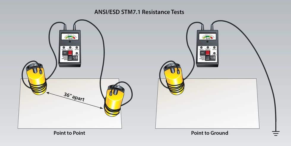
“ESD control floors and floor coverings shall have a point-to-point resistance and a surface-to-ground resistance of greater than 1.0 x 10E6 ohms and less than 1.0 x 10E9 ohms (ANSI/ESD STM7.1).”
Note: The 019f document supersedes a previous document (019d) where conductive flooring was considered acceptable.
Produced by UNINETT
- Working group on physical infrastructure
(No UFS103) Author: Stein Nygaard: May 2010 - Requirements for the Design of ICT Rooms – Best Practice Document European Requirement
- Section 4, subsection 9 – General Requirements for ICT rooms
- Recommended range:Floor coverings shall have anti-static or conductive properties and shall be earthed to prevent the accumulation of static charges. The resistance between any point in the floor covering and earth shall be from 1 to 10 MΩ, cf. NEK EN 50174-1:2009.
Please note: ESDA document ANSI/ESD S20.20 is not referenced above because the S20.20 standard is intended for program managers involved with the design and implementation of a static-control program in ESD-protected areas as part of a comprehensive program in electronics manufacturing environments. Here, we’re focusing on non-factory, end-user spaces, such as flight towers, networked offices, data centers and emergency dispatch call centers, where people work in proximity to operational/energized equipment.
Resistance Requirement by Application
| Category | Class-0 | Controlled Environments (ANSI/ESD S20.20) | End-User/Real-World |
|---|---|---|---|
| Maximum allowable resistance | 0 – ≤ 10E9 | 0 – ≤ 10E9 | 10E6 – 10E9 |
| Environment | Controlled/manufacturing ESD-protected areas (EPA) that handle ultra-sensitive devices or will in the future | Controlled/manufacturing ESD-protected areas (EPA) that are not Class-0 | Mission-critical areas that require ESD protection regardless of footwear |
| Applications | -electronics manufacturing service (EMS) facilities -cleanrooms -R&D environments | -microelectronics fabrication -circuit board assembly -manufacturing test and repair of electronics | -9-1-1 dispatch areas -data centers -fight command centers -networked offices -hospital/imaging -control rooms -labs -government offices -server rooms |
| Flooring options with regular footwear | N/A: Regular footwear prohibited; must use ESD footwear | N/A: Regular footwear prohibited; must use ESD footwear | -EC Rubber -ESD Carpet |
| Flooring options with ESD footwear or heel straps | -EC Rubber -ESD Carpet -Conductive Vinyl | -EC Rubber -ESD Carpet -Conductive Vinyl -Some Conductive Epoxy Coatings -Plastic Interlocking Conductive Flooring | -EC Rubber -ESD Carpet -Conductive Vinyl -Static-dissipative Vinyl Tile -Conductive Epoxy Coatings -Static-dissipative Epoxy Coatings -Plastic Interlocking Conductive Flooring -Plastic Interlocking Dissipative Flooring -Conductive High-pressure Laminate |
Measuring Electrical Resistance
We can predict how quickly or slowly an ESD floor will ground static charges by measuring its electrical resistance. Although the test method was designed by ANSI/ESD for use in evaluating flooring for electronic manufacturing and handling operations, the telecom and computer industries and the FAA use the same test method. Resistance and grounding standards, however, are industry-specific, as outlined above.
Before testing, both the flooring tiles and remaining elements for a mockup sample should be placed in a controlled chamber for several days with the humidity lowered to 12% RH. As we know, water is a conductor. At 40% RH, airborne moisture might affect and likely improve the performance of any ESD floor. In temperature-controlled environments, where the air is typically drier, floors will generally have higher resistance readings.
Testing at low RH removes any moisture from the flooring material and eliminates humidity as a variable in assessing performance. If a floor performs well at low humidity it will perform well at higher relative humidity points.
The resistance of both a flooring material and flooring system is measured in ohms.
To test the resistance of flooring materials, we use test method ANSI/ESD STM7.1-2013. This test measures the rate at which current passes across the surface of a floor tile, and predicts how well the floor itself will resist or conduct the flow of electricity.
Here is official description of the test method:
ANSI/ESD STM7.1
Floor Materials—Resistive Characterization of Materials. This standard says that flooring material must measure below 1.0 x 10E9 ohms to ground. The flooring material must also comply with the 2 parameters listed below:
One final note:
Resistance is only one of two required parameters for an ESD floor. To prevent random static events, ESD floors must perform two equally important functions:
- Provide a traceable path to ground of less than or equal to 1 billion ohms (≤ 1.0 x 10E9);
- Prevent static charges from accumulating as people walk (called walking body voltage).
Test Method Used to Measure Walking Body Voltage
ANSI/ESD STM97.2-2016
This document establishes test methods for the measurement of the voltage on a person in combination with floor materials and footwear.
* Visit this page for more information on walking body voltage.