What is Electrical Resistance?
[14 min read, 4 min videos]
We often field questions about resistance and walking body voltage: what do the terms mean? How do the properties differ? When evaluating an ESD floor, why is it necessary to test both?
What Is Electrical Resistance?
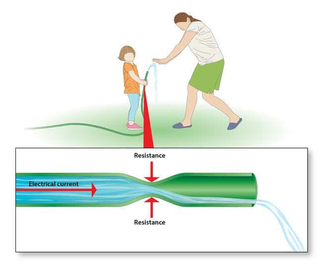
The terms “conductive” and “static dissipative” describe the approximate speed at which currents are likely to flow through or across a flooring material. Because conductive floors have less electrical resistance—are less able to slow or resist the flow of electricity—they allow charges to flow more quickly than static-dissipative floors.
What Determines if a Floor is Conductive or Dissipative?
To evaluate the conductivity of a flooring material, we measure its electrical resistance—using standard test method ANSI/ESD STM7.1. Electrical resistance is measured in ohms (Ω).
Floors/flooring materials measuring less than 1.0 x 10E6 Ω are considered conductive.
Floors/flooring materials measuring greater than 1.0 x 10E6 Ω and less than or equal to 1.0 x 10E9 Ω are generally considered static dissipative.
Conductive or Dissipative: Which Should I Specify or Use?
Buyers and specifiers often use the terms conductive or dissipative to evaluate or specify ESD flooring. At their highest and lowest ends, these categorizations are useful, in that overly conductive or overly dissipative floors will not provide optimal performance and, in some cases, may even put safety at risk.
There are, however, better ways to evaluate an ESD floor.
Like all electrical current, static electricity seeks its easiest path to ground. It would seem that the faster charges flow through a material the better. (In this scenario, conductive would win out over static dissipative.) But that’s not necessarily the case.
Mitigating factors—such as the chemical attributes of a flooring material; its propensity to generate (or inhibit) static charges; the shoes people wear when they walk on the floor; and the environmental conditions—all affect the performance of ESD flooring materials. These factors are more important—and more predictive—considerations than whether a floor is solely categorized as conductive or static dissipative.
According to the ESD standard ANSI/ESD S20.20, any floor with an electrical resistance measuring less than or equal to 1.0 x 10E9 ohms—a range that includes both conductive and static-dissipative materials—will conduct static electricity away from its surface and provide an adequate pathway to ground.
Why Do I Need a Floor That’s Electrically Conductive?
Regular—non-ESD—floors are insulative. Insulative materials stop or resist the flow of electricity, and cannot be grounded. With no pathway to ground, static charges stay in place, on the surface of the floor.
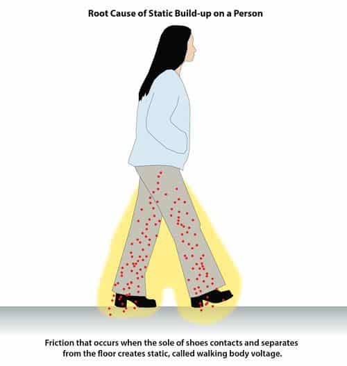
To feel a static discharge (a static shock)—the zing you experience when you touch a doorknob, for instance—the discharge must be at least 3500 volts. Yet a discharge of only 100 volts—in some cases only 20 volts, well below the threshold of human perceptibility—can disrupt data and damage or destroy the ultra-sensitive microcircuits in state-of-the-art electronic equipment.
How ESD Floors are Grounded and Why Grounding Matters
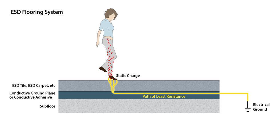
Grounding a floor—pulling charges downward, away from people and mobile equipment—prevents static from accumulating on the walking surface. How does that work?
Conductive elements like carbon or graphite are embedded in ESD flooring materials during the manufacturing process. ESD flooring materials are installed over a conductive underlayment, like conductive adhesive or metal access panels, which are attached (usually by copper strips) to an earth ground, such as an electric outlet or steel I-beam, forming a conductive ground plane.
Grounding an ESD floor
One copper grounding strap should be installed for every 1000 square feet of ESD flooring. Each room should have at least one grounding strap.
Step 1

Remove center screw on cover of AC electrical outlet using a screw driver.
Step 2
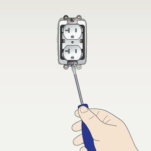
Locate and remove grounding screw inside AC electrical outlet.
Step 3
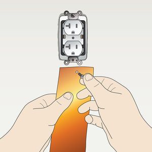
Punch small hole in 24″ copper grounding strap (provided with StaticWorx ESD flooring). The hole should be smaller than the head of the screw removed in Step 2.
Step 4
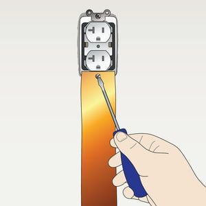
Secure copper strap to the AC electrical outlet with the same screw removed in step 2.
Step 5
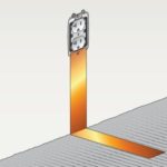
Fold copper at a 90-degree angle at the point where the wall meets the floor. Lay remainder of copper strap flat on the subfloor. The strap can be placed directly on the concrete subfloor in advance of installation or pressed into the conductive adhesive during installation.
At least 6 inches of copper should contact the floor. If the copper is applied directly to bare concrete or another subfloor, it will need to be covered with conductive adhesive during the installation.
Step 6
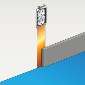
Cover copper strap on floor with conductive adhesive and new flooring material. For a cleaner installation, copper should be covered by wall base.
Step 7
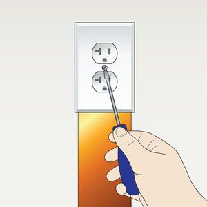
Finish installation by re-attaching AC outlet cover with screw removed in step 1.
The conductive elements in the floor draw static away from the surface of the floor, through the thickness of the flooring material. The conductive underlayment then transports charges across the ground plane, and discharges the current to ground.

Evaluating Conductivity: Measuring Electrical Resistance
Resistance: The Opposite of Conductivity
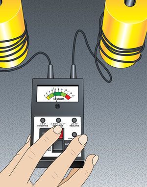
Resistance—the opposite of conductivity—refers to the capacity of a floor or material to stop, or resist, the flow of electricity.
All floors, regular and ESD, have some inherent electrical resistance. We measure resistance, in ohms (Ω), using standard test method ANSI/ESD STM7.1, to determine if a floor is sufficiently conductive (its resistance is not too high) to allow static to flow to ground.
The resistance of regular flooring materials, such as standard carpet, resinous coatings and VCT, is far too great to allow any flow of electricity. These floors, categorized as electrical insulators, cannot be grounded and will not discharge static.
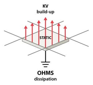
Some materials—static-dissipative rubber, for instance—dry out over time, which raises the electrical resistance of the flooring material (sometimes by enough to render the floor ineffective). Materials like “antistatic” or “low kV” carpet, which gain their conductivity from anti-stats applied during the manufacturing process also become more resistant as the factory-applied anti-stat wears off.
Standards for Electrical Resistance Vary by Industry and Application
As noted above, ANSI/ESD S20.20, for the electronics manufacturing and handling industries, requires the resistance of an ESD floor to measure < 1.0 X 10E9, or 1,000,000,000 ohms.
- S20.20 is a standard set by the ESD Association, a professional organization dedicated to advancing knowledge about and preventing damage from electrostatic discharge (ESD).
Strictly in terms of grounding static charges*, any floor with an electrical resistance measuring < 1.0 X 10E9 meets the resistive properties requirement of ANSI S20.20 and is considered acceptable for electronics manufacturing and handling applications.
- S20.20 also requires floors/flooring materials to inhibit charge generation—a completely different property.
While the test methods outlined in S20.20 are used across the board, for all applications, the standard itself applies only to electronics manufacturing and handling environments. This electronics industry standard should not be used for other industries—including flight control, explosives handling, data centers, and telecommunications environments.
Motorola R56, the industry standard for telecommunications spaces—mission-critical call centers, networked government offices, and 9-1-1 dispatch centers, for instance—and FAA 019f, the standard for flight towers and spaces using flight-tower equipment, require the resistance of flooring materials to measure between 10E6 and 10E9. More on this later.
✓ visual selector guide;
✓ walking body voltage/low static generation;
✓ resistance requirements and testing;
✓ ESD flooring comparison;
✓ industry standards & test methods;
✓ key ESD terms
The (Defunct) NFPA 99 and ANSI/ESD STM7.1 Yield Vastly Different Readings
Unlike the telecom and flight tower standards, ESD S20.20 does not specify a lowest acceptable resistance. For best practices, the flooring industry has historically set the minimum resistance at ≥ 2.5 x 10E4, or 25,000 ohms. This number was obtained from a now defunct NFPA test method, requiring 500 volts of DC current to be applied to the surface of the flooring material during the measurement of resistive properties.
To say a floor measuring 2.5 x 10E4 meets NFPA 99 and is therefore safe for any environment is, at best, misleading.
In accordance with ANSI/ESD STM7.1, 10 volts of AC current are applied to a flooring material. Ohm’s law states: voltage is inversely related to resistance. The lower the voltage, the higher the resistance. The higher the voltage, the lower the resistance.
With only 10 volts of applied current, a floor will easily stop the flow of current, yielding a relatively high electrical resistance value. Apply 500 volts of current and the same floor will have a much harder time stopping electrical charges (resistance will be lower).
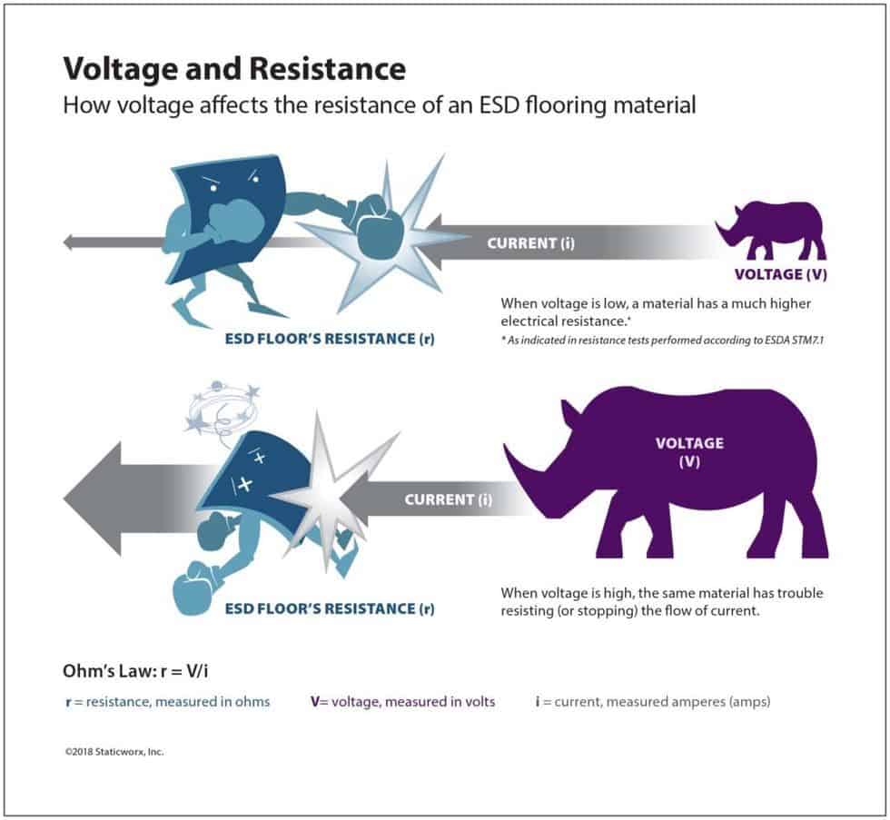

Suppose, with 10 volts of applied current, a floor measures 2.5 x 10E4 ohms. Tested at 500 volts, in conformance with the defunct NFPA 99 test method, that same floor will have far less resistance—in fact, according to tests performed in an independent lab, it could measure as low as 2500 ohms.
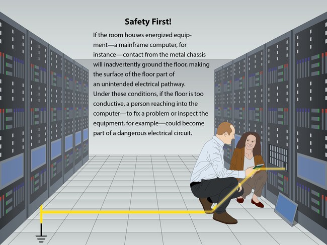
This means, the floor could support excessive/dangerous electrical currents; in the event that a person were to come into contact with live voltage while also in contact with the grounded floor, they could receive a serious electrical shock. For safety reasons, in end-user environments that house energized equipment, such as telecom spaces, server rooms, or FAA flight towers, where ESD-protective footwear is not required, floors with extremely low electrical resistance should not be installed.

An independent lab tested the resistance of conductive and static-dissipative carpet samples with 10 volts and at 500 volts of applied DC current. Here are the results:
Conductive Carpet Tile, Black Polyolefin Back
| Sample | 10 Volts | 500 Volts |
|---|---|---|
| Sample 1 | 7.5 x 10E4 7.2 x 10E4 | 1.6 x 10E4 1.4 x 10E4 |
| Sample 2 | 7.5 x 10E4 6.9 x 10E4 | 1.4 x 10E4 1.3 x 10E4 |
| Sample 3 | 5.0 x 10E4 6.0 x 10E4 | 1.4 x 10E4 1.0 x 10E4 |
Static-dissipative Carpet Tile, Brown Backing
| Sample | 10 Volts | 500 Volts |
|---|---|---|
| Sample 1 | 1.8 x 10E6 | 1.1 x 10E6 |
| Sample 2 | 1.5 x 10E6 | 8.0 x 10E5 |
The Sweet Spot
To protect people working with or near energized equipment, government standards such as FAA 019f, and industry standards, like Motorola R56, require resistance above 1 x 10E6. ANSI/ESD S20.20, on the other hand, does not site a minimum resistance.
Why do resistance standards differ?
Electronics manufacturing and handling environments have mandates and process controls—strictly enforced—requiring the use of special ESD-protective footwear. The built-in resistors in static-protective sole, heel and toe straps and ESD shoes protect the wearer from electrical shocks.
In telecom spaces, flight towers, data centers, as well as hospitals, government offices and other end-user environments, there are no footwear requirements. In those spaces, people wear regular street shoes, which offer no protection and—if those shoe soles are also conductive—may even contribute to the problem.
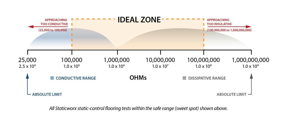
While resistance requirements vary, the optimal reading, what we call “the sweet spot,” is mid-range—between 10E5 and 10E8. In this range, even if humidity goes up, resistance will remain well within a safer zone, and if environmental factors raise the resistance of the floor, it will still be conductive enough to discharge static electricity safely and effectively to ground.

Get in Touch
The form below will help us better understand your needs and get you as quickly as possible to the right person. We look forward to helping you solve your static problem!
You can expect a response within 24 hours. For faster service, please give us a call: 617-923-2000
"*" indicates required fields
Visit our privacy policy to find out how we process data.
Learning Center Articles
- ESD Basics
- Installation & Maintenance
- Selecting & Specifying an ESD Floor
- Technical Information
- 7 Common Mistakes Selecting an ESD floor
- A Guide to ESD Flooring Selection
- Avoid Costly Failures: What You Need to Know When Specifying ESD Flooring
- Choosing ESD Flooring for:
- ESD Footwear: What Is It and When Is It Necessary?
- ESD Footwear for Electronics Manufacturing and Handling Applications
- Facility Managers’ Guide to Selecting ESD Flooring
- The Need for Due Diligence in Specifying Static-Free Flooring
- Standard of Care for Specifying Floors in Mission-Critical Spaces
- Understanding the Hidden Costs of ESD Flooring

StaticWorx high-performance static-control floors protect electronic components, explosives, and high-speed computers from damage caused by static electricity. ESD flooring is part of a system. Choices should always be based on objective, researched evidence. When you partner with us, we look at all possible items that may need to integrate with the floor, and, focusing on your goals and objectives, help you find the right floor for your application.


